Which Standard Should You Consider When Designing Portable Wireless Charging Systems?
Introduction
Smartphone technologies are the key indicators of consumer electronic trends. New technologies and features continue to emerge such as USB type C, 4K video, and immersive VR gaming. Wireless charging is one of these technologies that has been in use since late 2000, but is still not used by the masses in smartphones. The industry generally agrees that the reason behind it is the eco-system; the standard. There are multiple standards in the world, but their technologies are incompatible at present.
The Standards
Currently there are two global organizations, but three standards for mainstream consumer electronics. In 2008, the Wireless Power Consortium (WPC) established the Qi wireless power standard based on Magnetic-Induction (M.I.) power transfer technology. The Power Matter Alliance (PMA) established the PMA standard based on a very similar M.I. technology. All For Wireless Power (A4WP) established a standard based on a different Magnetic-Resonant (M.R.) power transfer technology.
PMA and A4WP merged in 2015 and was named the Airfuel Alliance in early 2016. Despite the merger, the Airfuel Alliance continues to have two incompatible standards: Airfuel-Inductive and Airfuel-Resonant.
As of April 2016, WPC has 226 members with 844 certified products. Over 30 countries have deployed Qi products including China, Taiwan, Hong Kong, North America, Europe, South Korea, and Japan. The Airfuel Alliance has 149 members and 62 certified products. The main players in the Airfuel Alliance are located in North America and South Korea.
The Technologies
The Qi and Airfuel-Inductive standards both use M.I. technology that relies on tight coupling coils of magnetic fields transfer. They are very similar except for the operating frequencies and communication protocols for wireless power transfer operations. The Qi operating frequency is between 110 kHz and 205 kHz and the Airfuel-Inductive frequency is between 235 kHz and 275 kHz. The Airfuel-Resonant standard employs a different M.R. technology that is characterized as loosely coupled coils of magnetic fields transfer operated at 6.78 MHz.
Despite the name difference, M.I. and M.R. technologies are similar in many ways, which should become clearer later in this paper. Both technologies use transmitter and receiver antennas called Tx and Rx coils, and rely on an alternating magnetic field generated in the Tx coil coupling into the Rx coil for wireless power transfer in close proximity. Both technologies fall under the inductive coupling and near-field power transfer categories.
As shown in Fig. 1, the alternating current first conducts in the transmitter coil and infinite imaginary magnetic fields loop around it. With a receiver coil in close proximity, some of these magnetic fields are captured into the Rx coil. This action induces the alternating current in the receiver coil, which is known as the wireless power transfer.
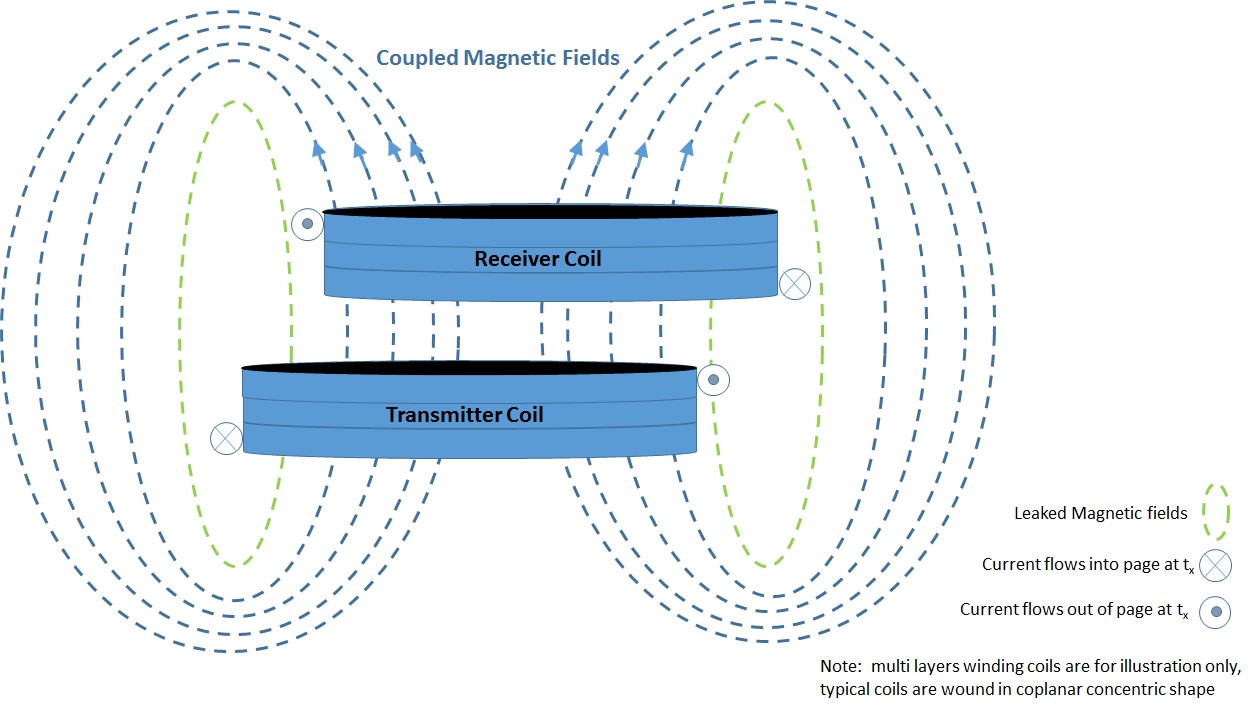
Fig. 1. Conceptual wireless power transfer.
Magnetic flux is a measurement of how much magnetic field passes through the Tx and Rx coils. The higher the magnetic field passing through the Tx and Rx coils, the higher the flux that enhances the power transfer. Near-field wireless power transfer technologies apply the same principle of the ideal transformer for power transfer without the metal core, which confines the magnetic field transfer from the primary to the secondary side winding. It is therefore the challenge for the wireless power technology to capture as much magnetic field in the air between the Tx and Rx coils as possible in order to increase the magnetic flux for optimizing the power transfer.
Wireless power is a complex subject; the numbers of variables that the designers need to deal with can be overwhelming. Some variables are inversely related and some have nonlinear effects. The variables that affect wireless power transfer efficiency are the size of the Tx and Rx coils, their positions and gap, the coil material, diameter, length, number of turns, number of layers, the tuning capacitor value and the capacitance coefficient, the resonant frequency, skin effect, proximity effect, magnetic shielding materials and configurations, temperature, and more. These variables relate to the coils’ DC and AC resistances, which are the self and mutual inductances that dictate the power transfer performance. Fortunately, all of these variables can be summed up by two important factors, which are the Coupling factor k and the Quality factor Q. It can be proven that near field inductive coupling power transfer efficiency [1] is
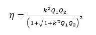
(1)
where k is the coupling factor between the Tx and Rx coils, and Q1 and Q2 are the Quality factor of the Tx and Rx coils, respectively.
The k and Q factors are figure-of-merit because if we can make the term k2Q1Q2 much larger than 1, then the power transfer efficiency approaches 1. It is virtually impossible to achieve 100% due to the numerous variables described. The k and Q factors apply to both M.I. and M.R. technologies with different degrees of influence on power transfer efficiencies. An example of measured k factors is presented in [2]. The Q factor can be measured in certain LCR meters. In practice, k and Q are usually estimated.
The Coupling factor k is unit-less, with the greatest number of 1 when all the magnetic fields pass through the Tx and Rx coils in maximum strength. As seen in Fig. 1, some of the magnetic fields cannot be captured by effects such as coil alignment and gap. Some fields travel longer distances than others because their magnetic field strengths are relatively weak. In M.I. technology, the Q factor, which will be explained later, is essential, but the k factor is far more important than the Q factor. In general, the coupling factor is best when the Tx and Rx coils’ shapes and sizes are matched, coils are aligned, and are in a close gap within 10 mm in the x, y and z directions or tighter. Currently, M.I. technology for smartphone applications reaches about 80% efficiency from AC input to DC output.
The Quality factor Q is also dimension-less. High Q indicates a low rate of energy loss relative to its stored energy in the power coil. Typical Q in M.I. designs is between 30 and 50, and typical Q in M.R. designs is between 50 and 100. The Q factor increases in frequency, peaks at the resonant frequency, then falls sharply and equals to 0 when it reaches the self-resonant frequency. Further increases in frequency alters the coils’ inductive characteristic to capacitive. Optimum frequency for the maximum Q occurs at the resonant frequency. Since the coil is inductive, it is best use a tuning capacitor to tune the LC to the resonant frequency. Also, Tx and Rx coils are rarely identical nor perfectly aligned, and the Q factor is unique to each coil.
In M.R. technology, the k factor is generally not at its optimum since the coils’ alignment and gap requirements are looser. On the other hand, the Q factor is critical. M.R. coils generally have few windings and also require a gap between adjacent coils, as shown in Fig. 2, to reduce the proximity effect. The proximity effect is a phenomenon in high frequency operation such that the influence of the adjacent conductor can reduce the effective cross-sectional area of the measuring conductor for the flow of the current; it therefore increases the AC resistance that affects the power transfer. In addition, it can be proven that the optimum Tx coil radius R is
R = D (2)
where D is the distance between the transmitter and receiver coils for optimum near field inductive coupling power transfer [1]. Since the goal of M.R. technology is to achieve spatial freedom with looser coil alignment and proximity, M.R. coil size is generally larger than the M.I. coils. Figure 2 shows tri-mode coils where the inner and outer coils are for M.I. and M.R. technologies, respectively. Since M.I. relies on tight coupling coils in close distance, equation (2) does not affect M.I. technology as much as it affects M.R. technology.
M.R. coupling also allows a single transmitter to conduct power transfer to multiple receivers. In principle, M.R. technology can yield satisfactory power transfer, but the design challenge is very high because of the narrow range of optimum Qs.
Development
In M.I. and M.R. technologies, semiconductor makers are mainly from the US, Japan, Europe, Taiwan, and Hong Kong. Since different and incompatible wireless power standards exist, few semiconductor companies develop multimode transmitter and receiver ICs. Dual-mode devices include Qi + Airfuel-Inductive transmitters and receivers. Currently, Tri-mode devices are Qi + Airfuel-Inductive + Airfuel-Resonant receivers only. Multimode wireless power solutions address the dilemma of multiple standards. On the other hand, M.I. and M.R. technologies employ unique coil designs where the coils cannot be shared. [refer to the Tri-Mode Wireless Power Coils in Fig. 2 (courtesy of TDK).] The center coil is used for both Qi and Airfuel-Inductive standards for 5 W operations. The outer coil is dedicated to the Airfuel-Magnetic standard for 6.5 W operation. The coil module dimension is 75 mm x 60 mm. The multimode operation increases the complexity and cost of the coil and system designs.
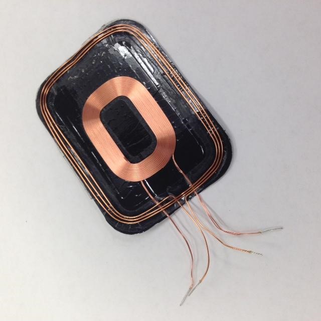
Fig. 2. Tri-mode wireless power coils, where the inner coil is for M.I. Qi and Airfuel-Inductive operations and the outer coil is for M.R. Airfuel-Magnetic operation (courtesy of TDK who provided the tri-mode wireless power coils picture).
Other new developments in wireless power technology include phase-shift control. Driving Tx and Rx coils involves inductive switching with the AC voltage leading the AC current to a maximum of 90 degrees. Researchers are working on phase-shift control in order to align the AC voltage and current waveforms for optimizing the power transfer efficiency.
WPC also has several new developments. It has a task force working on publishing the resonant extension in the Qi specification. Their goal is to use the same M.I. Tx and Rx coils for M.R. applications at low frequencies to leverage system designs. WPC also adds a Shared Mode extension to allow multiple receivers to be powered by a single transmitter. In addition, WPC is also working on a 60 W–200 W version of wireless power transfer for power tools, drones, and laptop computer applications.
In Airfuel-Resonant technology, at least one company has been proposing GaN FET to replace MOSFET in the transmitter inverter design to reduce the loss in the switching circuit.
In the future, a wireless power transceiver (transmitter and receiver combined) IC is a possibility. Applications include a battery bank where the battery is a receiver when it is being charged from a transmitter base. The battery becomes a transmitter when it is used to charge a receiver device.
Reliance by employers on complying with standards for introducing their products to the marketplace
Companies who embrace wireless charging usually adhere to standards. Standards enable the expansion of the eco-system that can lead to the mass adoption of the technology.
In addition, researchers, semiconductor companies, and coil makers designing wireless power solutions and contributing to the standards have spent years understanding the dynamics of the technology. As a result, companies who follow the standards and apply reference designs not only avoid reinventing the wheel, but also increase the chance of design success.
Toshiba semiconductor has been providing wireless power solutions since 2012. The company follows the Qi standard and has just launched its fourth-generation chipset, the TC7718FTG transmitter and TC7766WBG receiver, for Qi 15W wireless power applications.
Summary
Standards enable the development of the eco-system. It is imperative that users be able to charge their phones in places like airports or coffee shops seamlessly without understanding the standards issue. Given time, the market should self-regulate such that wireless power standards should converge.
Any wireless power technologies offer convenient wireless charging possibility. However, there is no one-size-fits-all wireless power technology exists that meets all the system cost, size, and efficiency requirements and yet offers the ultra-convenient feature of wireless charging from a distance. As a result, the standard selection depends on the application requirement. For applications that demand maximum efficiency and a tighter design footprint, Qi and Airfuel-Inductive are the standards. For applications that demand charging without strict Tx and Rx coil alignment and allow for a few centimeters coil-to-coil gap freedom, the Airfuel-Resonant coupling is the standard at present and perhaps Qi resonant in the future.
References
[1] T. Sun, X. Xie, and Z. Wang, Wireless Power Transfer for Medical Microsystems. New York: Springer, 2013. [2] Eberhard Waffenschmidt, Qi Coupling Factor. https://www.wirelesspowerconsortium.com/technology/coupling-factor.html

Alan Li alan.li@taec.toshiba.com Toshiba Semiconductors
Alan Li graduated from Florida International University with a BSEE degree. He started his applications engineer career at National Semiconductor, which was later spun off as Fairchild Semiconductor. Alan has also worked at Analog Devices and Intersil in applications and marketing roles. Currently Alan is a senior business development manager at Toshiba Semiconductors where he is responsible for wireless power, motor control, and a variety of analog products for the American market. Alan has over 20 years of analog semiconductor experience in which he defined numbers of analog products such as DAC, digital potentiometers, LED drivers, and power management ICs for the industry. Alan has also published a number of articles and application notes in digital-to-analog converter and digital potentiometers applications.